Memaparkan catatan dengan label METHOD STATEMENT. Papar semua catatan

14 Okt 2012

METHOD STATEMENT INSTALLATION OF SHEET PILES


Ohayo gozaimasu


The installation of sheet piles are the famous type of temporary works for the construction of  building or bridge during foundation works such as pilecap structural.   Steel sheet piles are long structural sections with a vertical interlocking system that creates a continuous wall.

The walls are most often used to retain either soil or water. The ability of a sheet pile section to perform is dependent upon its geometry and the soils it is driven into. The pile transfers pressure from the high side of the wall to the soil in front of the wall.

There are permanent and temporary applications. Permanent sheet piles remain in the ground and serve as permanent retaining structures. Temporary sheet piles are designed to provide safe access for construction, and are then removed.

However in the construction works today with amount of contract sum too  low due to the tight competition during tender process and in order to secure profit margin sometime we overseen and under estimate the ground condition without take considered the temporary cost such as sheet piles.

If the  contract awarded  based on the bill of quantities it so lucky if the client could agree on the variation order for the additional works. Sometimes it so hard to fight because in the normal contract document all the temporary work such as providing access and etc within period of construction have included under general works and preliminaries item.

25 Jul 2012

METHOD STATEMENT OF DOUBLE GIRDER OVERHEAD CRANE

How to install Rail Mounted or EOT Gantry Cranes

Ohayo gozaimasu


Electrical Overhead Travelling (EOT) cranes or Gantry Cranes are commonly found in factory applications such as steel yards, paper mills or locomotive repair shops. The EOT gantry crane functions similarly to an overhead bridge crane, but has rails installed on the ground and gantry-style legs to support the crane. Capacities range from 2 to 200 tons, and sometimes even greater capacities. Most are electrically powered and painted safety yellow.


Overhead cranes, sometimes also called bridge cranes, are cranes with a hoist traveling along the bridge between parallel runways. They are designed to meet the medium to heavy industrial lifting requirements, covering all parts of manufacturing process.


With this post i just want to share knowledge for installing the overhead gantry during construction.


1.0   PLANT AND MACHINERIES

1.0     60 ton mobile crane       -  1 Nos
2.0     trailer                           -  1 Nos
3.0     20 tonne x 19m length Overhead Crane   -  4 Nos
                                    Model : CXT6062P6FO
                                    Min. Loaded Hoisting Speed = 4/0.7m/min @ 60% ED
                                    Hoist Group : Fem 3m.
                                    2 Nos girder : 9.00 Tonne ( 4.5Tonne/girder)
                                    1 nos of hoist : 2.30Tonne
                                    2 Nos end Carriages:1.17Tonne

2.0   DOULBLE GIRDER E.O.T CRANE INSTALLATION PROCEDURE (BY MOBILE CRANE)

            A. Crane Erection Inside Building

1.0   proposed indicating area required site clearance for mobile crane and trailer parking for the unloading, assembly and erection of overhead crane  (Area of 30m(length) x 20m ( width-crane span) at each bay).
2.0     Erection work will be carried out inside building.

            B.  Crane Installation

1.0          A complete double girder crane is made up the following major part:
i)                    Girders
ii)                  End carriages
iii)                Hoist
iv)                Flat cable power supply and mobile control system
v)                  Other smaller items like long travel control box, end stopper, limit switch and etc.

2.0          Upon unloading girders from trailers, the girders will be placed on stools at two ends for
subsequent crane assembly work.

3.0      Assemble end carriages to 1st girder ( power supply side) and tigten bolts and nuts
Note: Girders and end carriages are match-made in factory with matching marks punched on each item. Re-match the matching marks during installation at site.
4.0      Strap a short sling around the girder and lift up the girder slightly by using mobile crane   
(refer Appendix A).
Note: When strapping short sling, using soft material around the girder to protect it from
being scratched.
5.0      Site touch up painting.

6.0      Tie 2 manila ropes at each of the end carriages.

7.0      Rotate the girder so that it makes an angle of approx.45º with the runway and are position in between columns.

8.0      Lift up the girder at the center until it clear the runway. Using the nylon ropes rotate the
crane from 45º to 90º ( with the runway ) ( refer to Appendix B ) and slowly lower crane
onto runway rails
9.0      Remove all ropes

10.0      Repeat step ( 4) to ( 9) for another girder
11.0      Lift up the hoist with mobile crane and place on top of girder
12.0      Fix up all electrical wiring and downshop power supply
13.0      Test each movement of the crane.
Note: Depends on the availability of power supply.

3.0                   SAFETY AND HEALTH

1.0       Regulations

All site activities shall comply strictly with UEMC Project Health and Safety Plan regulations and requirements. All staff will also be familiar with the Construction Crisis Team’s Handbook.

             2.0       Launching Safety Briefing

A safety briefing will be conducted by the launcher prior to the launching to ensure that all people involved are familiar with the works (The Designed Launcher will be fully in charge during the launching activity). The safety officer will then brief the workers on the general hazards of slab launching.

3.0       Equipment Checks

The safety officer will check and ensure that all cranes are fully operational and that there is no irregularities prior to the launching. The launching will be halted if any irregularities are observed.

4.0       General Safety

All workers are to wear PPE equipments such as  safety helmet and safety shoes within working area. All safety issues will be governed by the Health and Safety Plan and adhered to strictly.

5.0       Environment Issues

The Environmental Management Plan will be adhered to strictly on site.

9 Jul 2012

Method Statement of Load Test using Osterberg Cell ( O-Cell)


Method Statement of Load Test using Osterberg Cell ( O-Cell)

,

Ohayo gozaimasu

It has been more than 2 week I not update my blog for the construction field post. As per previously articles I have mentioned about load test for pile by using kentledge system method and reaction pile method. Currently with the advance technology and competitive in construction in term of costing and time impact, I would like to share my experience with another method of load test by using bi-direction static load test.

Static load testing, where loads are applied vertically to the top of the pile and often referred to as ‘top down testing’, has been used for many years and has become a ‘standard’ test for the world of foundation engineering.

The method, although well developed, cannot be used under certain circumstances, magnitude of load being a particular issue. There is a finite limit to the load capacity that can be applied with either kentledge, the use of reaction piles or anchors, and as the loads increase, the costs escalate dramatically.


26 Jun 2012

METHOD STATEMENT OF COMPRESSION MAINTAIN LOAD TEST USING REACTION PILES


In construction of bridge and building works, most of civil engineer must start and gain the common of static load test of piles. Based on previous articles i have mentioned with the method of load test using kentledge dead load which are commonly used in construction.

26 Mei 2012

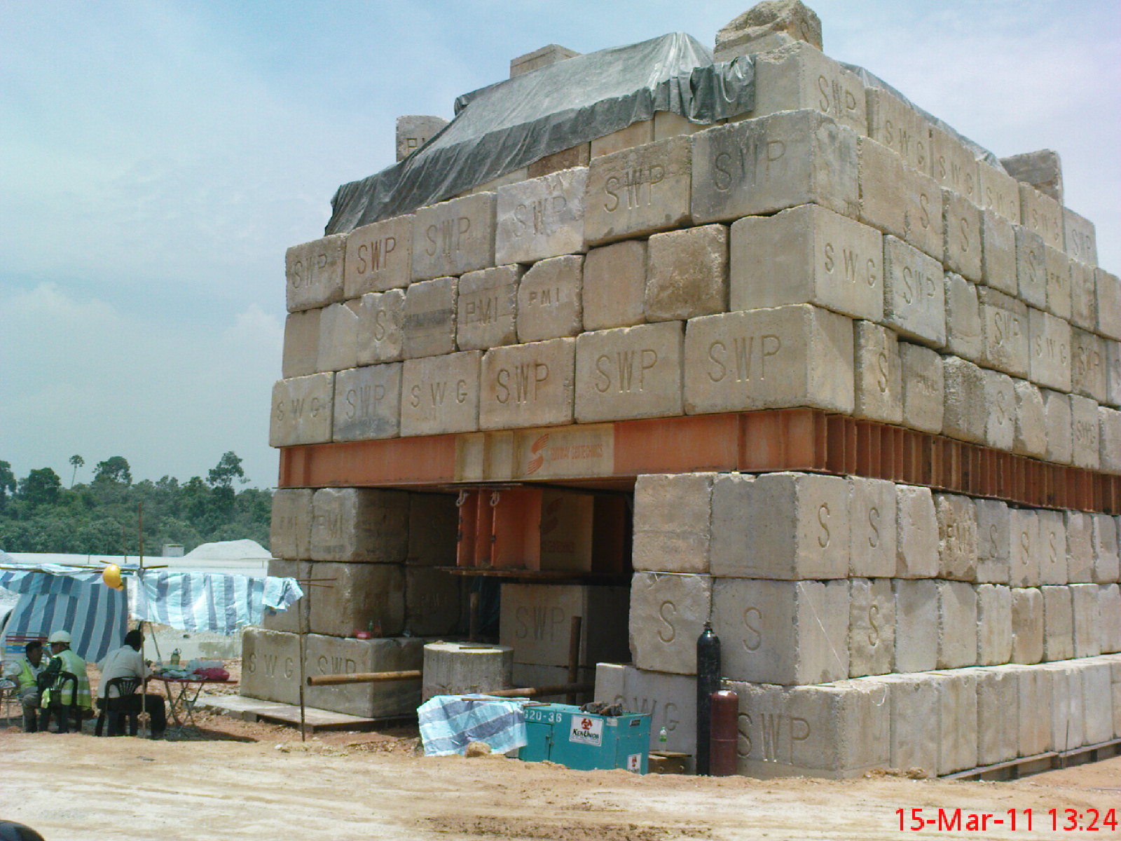
METHOD STATEMENT FOR KENTLEDGE MAINTAIN LOAD TEST


I would like to share my experience in testing of piles during construction. The common test which 
implemented at site in order to check the performance of piles is kentledge Load Test / Static Load Test.  

The main objective of the load test is to study the performed working barrette piles when the 2 time
working load apply to the selected tested pile.

17 Apr 2012

METHOD STATEMENT FOR DRIVEN SPUN PILES


Method Statement for driven of spun piles is generally describes the method used to the installation of  driven precast  with various size diameter of  spun piles Grade 80N/mm2. Under this method statement will describes the procedures of driven piles , penetration or set that is required within the given scope of works. 


24 Feb 2012

FIELD DENSITY TEST - EARTHWORK


The first test that i really lesson during first day working as site engineer on 1999 was to conduct Field Density Test for earthworks. I still remember that day until today because i realize that even though i  graduated in Civil Engineering  but i fail to complete my first task.

Field Density Test is carry out at site to determine the  Dry Density Soil on compacted soil.  There are two (2) method currently implemented at site as followings:-

  1. Core Cutter Method  (B.S. 1377 Test Method –Test 15(D)) 
  2. Sand Replacement Method (B.S. 1377 Test Method – Test 15(A)) 

15 Feb 2012

Method Statement Of Vibro Replacement Stone Column


INTRODUCTION OF VIBRO STONE COLUMN TECHNIQUE

History of ground treatment  was establish by Keller for almost 150 years of excellence in ground engineering.

24 Jan 2012

SONIC LOGGING - CONSTRUCTION FIELD


CONSTRUCTION FIELD

Just to share knowledge in engineering 

METHOD STATEMENT FOR SONIC LOGGING

General

Sonic logging is a technique used to detect defects in the concrete structures such as bore piles, caissons, barrettes and diaphragm walls.