
CONSTRUCTION OF TEMPORARY BRIDGE.
 In Construction, the most important thing during planning stage are to identify and observed the access and temporary works need to be implemented during construction stage. As Construction Manager, it is necessary to understand the obligation of contractor as per Contract Document for the temporary works items in order to avoid the cost implication to the company.
Sometimes during tender stage, the temporary works normally have been included in the preliminaries items as lump sump quantity. It means all cost for the Temporary works in whatsoever works requirements for the completion of the project shall be included under contractor obligation in lump sum amount.
If the contract is a design and build contract, it is clearly stated under contractor's general obligation, the contractor shall provided all design, services, labour, material, contractor's equipment, temporary works, transport to and form and in or about the site and everything whether temporary nature required in and for such design,construction and completion so far as the necessity for providing the same is specified in or reasonably to be inferred for the contract.
However when come to sub-contractor contract sometimes the contractor misunderstanding that the major temporary works and access shall be provided by main contract unless it have been agreed as back to back basis. It so tricky because the temporary works cost can be affected the overall profit margin for the project. Some contractor did not realise the content inside the contract document can trap them into trouble when the site condition especially the ground condition is too bad and requires a lot of temporary works such as temporary cofferdam, temporary jetty, staging or temporary bridge in order to complete the works within completion period.
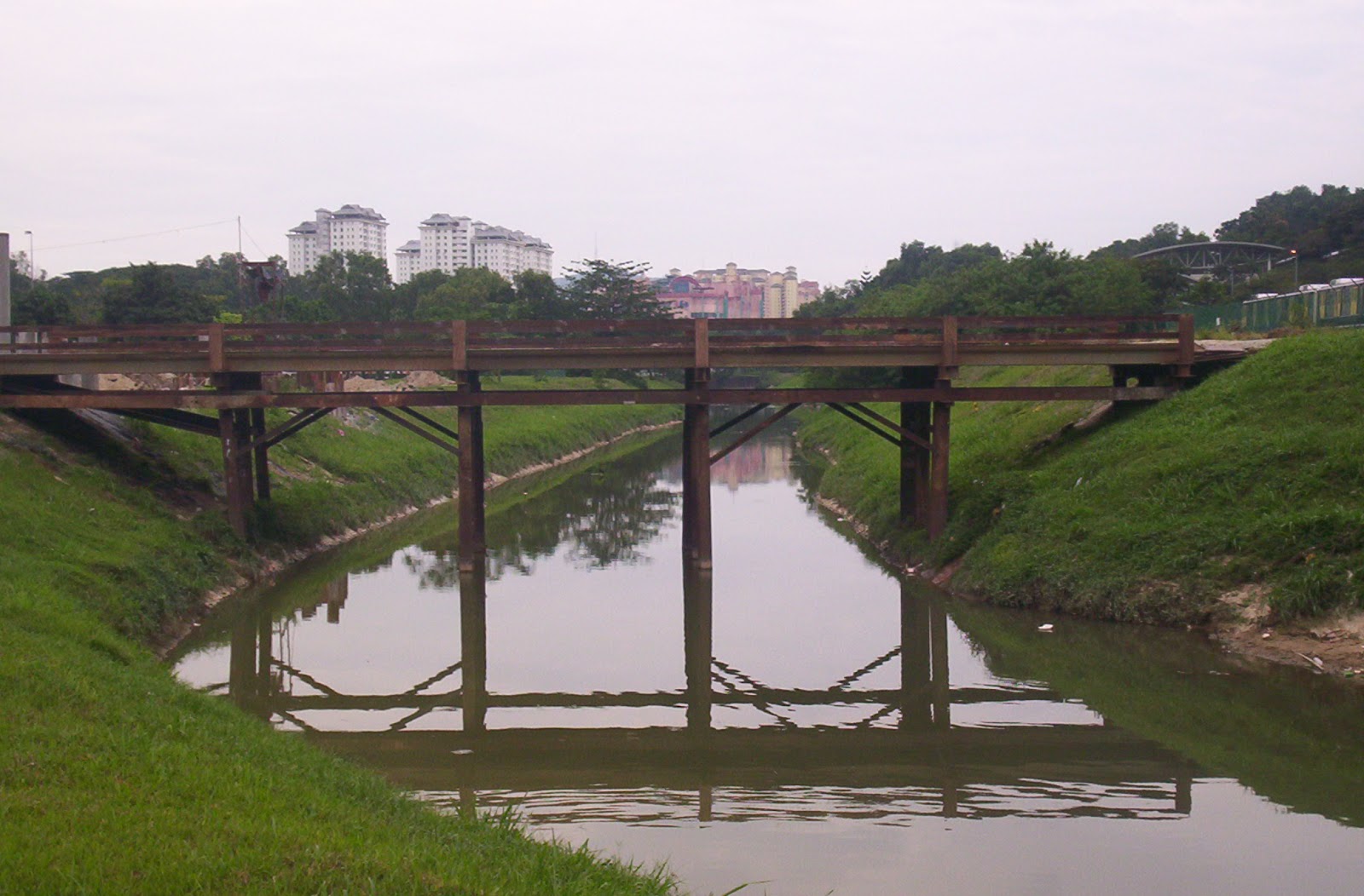
One of my project site that required the temporary works as composite bridge during construction of KL - Putrajaya Highway under Package 5 : Kesas Interchange. The temporary bridge cross sungai Kuyoh nearby Sri Petaling LRT Station need to construct due to the unavailable access from the other side of river which block by LRT railway.

The design of temporary bridge using steel structure and composite concrete so that it easy to construct and dismantle.


The Completion of temporary Bridge ( Photo Below ) ready to use for permanent works.


 In Construction, the most important thing during planning stage are to identify and observed the access and temporary works need to be implemented during construction stage. As Construction Manager, it is necessary to understand the obligation of contractor as per Contract Document for the temporary works items in order to avoid the cost implication to the company.
Sometimes during tender stage, the temporary works normally have been included in the preliminaries items as lump sump quantity. It means all cost for the Temporary works in whatsoever works requirements for the completion of the project shall be included under contractor obligation in lump sum amount.
If the contract is a design and build contract, it is clearly stated under contractor's general obligation, the contractor shall provided all design, services, labour, material, contractor's equipment, temporary works, transport to and form and in or about the site and everything whether temporary nature required in and for such design,construction and completion so far as the necessity for providing the same is specified in or reasonably to be inferred for the contract.
However when come to sub-contractor contract sometimes the contractor misunderstanding that the major temporary works and access shall be provided by main contract unless it have been agreed as back to back basis. It so tricky because the temporary works cost can be affected the overall profit margin for the project. Some contractor did not realise the content inside the contract document can trap them into trouble when the site condition especially the ground condition is too bad and requires a lot of temporary works such as temporary cofferdam, temporary jetty, staging or temporary bridge in order to complete the works within completion period.
One of my project site that required the temporary works as composite bridge during construction of KL - Putrajaya Highway under Package 5 : Kesas Interchange. The temporary bridge cross sungai Kuyoh nearby Sri Petaling LRT Station need to construct due to the unavailable access from the other side of river which block by LRT railway.

The design of temporary bridge using steel structure and composite concrete so that it easy to construct and dismantle.


Method Statement for Construction of Temporary Bridge
1. SCOPE OF WORKS
1.1
This work method statement
outlines the work sequence and machinery requirement for construction (and
subsequently dismantling) of temporary composite bridge across Sungai Kuyuh in Kuala Lumpur–Putrajaya
Highway
1.2
The description of the proposed
temporary composite bridge is as per below:-
a)
|
Total bridge
length
|
30
|
m
|
b)
|
Individual
span length
|
6
|
m
|
c)
|
Number of span
|
5
|
spans
|
d)
|
Number of pier in water
|
2
4
|
piers / 4 nos.
H-pile (after river training works)
piers / 8 nos.
H-pile (prior river training works)
|
e)
|
Foundation
|
300x300x94
kg/m UC / H-pile
(estimated
length per no. at refusal = 12m)
|
|
f)
|
Crossbeam
|
300x300x94
kg/m UB (minimum length per no. = 6m)
|
|
g)
|
Deck system
|
4
|
nos./span 500mm
thk. X 1.5m width x 6.0m length precast R.C. double T-beam
|
2. CONSTRUCTION PROCEDURE
2.1
The alignment of the temporary
bridge and locations for steel H-piles shall be demarcated by a competent
surveyor.
2.2
The locations for H-piles shall
be free of pre-cast concrete block (existing protection / revetment system
along the river bank), boulder and any other form of visible obstructor.
2.3
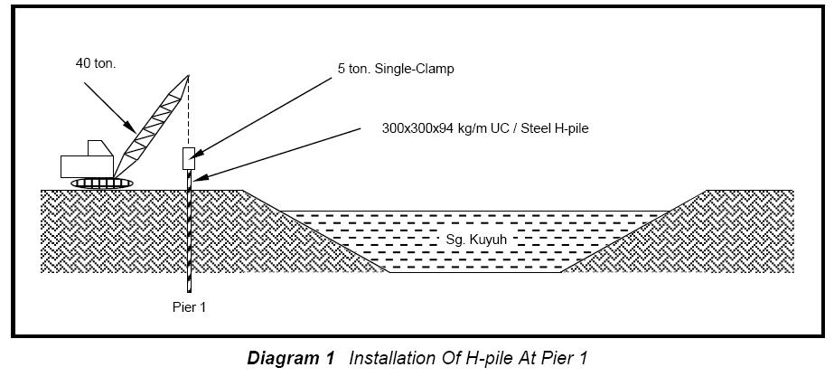
Construction of the temporary
bridge shall be kicked-off with installation of H-piles at Pier 1 (at the river
bank). It shall be carried out using a 40 tonne crawler crane and a 5 tonne
single-clamp vibro hammer. Kindly refer to Diagram 1.
2.4
The vertically for the said
H-piles shall be checked regularly by means of a spirit level.
2.5
The H-pile shall be driven to
refusal and shall be cut-off at RL 30.37m. This is to ensure that the lowest
point of the bracing or tie (in which to be installed at 2.20m below the said
cut-off level) is above RL 27.87m (high water level, Q100).
2.6 4 nos. of 0.5m H x 1.5m W x 6m
L precast R.C. double T-beams shall then be launched to span across the steel
crossbeam. The steel base plates of the precast beams shall be welded to the
steel crossbeams. Kindly refer to Diagram 2.
2.7 Bracing and tie (I300mm x
300mm) shall be installed and welded as per the details in the approved shop-drawings.
2.8 Backing piece (12mm thk. steel
plate normally) shall be welded to the H-piles at Pier 1 prior receiving earth
to form temporary ramp. This ramp is to enable the crawler crane to move on top
of the temporary bridge for construction of the next span.
2.9
Item 2.1 -- 2.7 shall be
repeated for construction of the subsequent span and complete the overall
temporary bridge as shown in Diagram 3.
2.10
Wedge metal plates (opposing
the flow direction) shall be installed at the H-piles at the upstream face to
minimise back-water-effect.
2.11
While the temporary bridge is
in place, regular check shall be conducted to ensure that the piers in water
remain free of water born debris.
3. CONSTRUCTION
PROCEDURE
3.1
The temporary bridge shall be
dismantled after completion of Ramp 4,
Ramp 6 and the Mainline.
3.2
The earth fill ramp (at LRT’s
side) shall be excated by an excavator as shown in Diagram 4. The excavated
material shall be disposed off site.
3.3
Backing piece, precast R.C. double
T-beams, steel crossbeam and bracing / tie shall be detached from the H-piles
at Pier 5 and Pier 6.
3.4
H-piles at Pier 6 shall be
extracted by means of a 40 tonne crawler crane and a 5 tonne vibro hammer.
Kindly refer to Diagram 5.
3.5
Item 3.3 & 3.4 shall be
repeated to dismantle the subsequent span.
3.6
In the event of difficulty in
the H-pile extraction work, higher capacity machinery and equipment (50 tonne
crawler crane with 8 tonne single-clamp vibro hammer for example) shall be
deployed.
4. PLANT/EQUIPMENT REQUIREMENT
4.1 40 tonne crawler crane
4.2 5 tonne vibro hammer c/w generator
4.3 Welding machine
4.4 Welding
and oxy-cutting accessories.
5. SAFETY
& HEALTH
5.1
General
Safety
The Site Manager will have overall responsibility for safety. The
construction area shall be isolated and fenced. Therefore, the danger of injury
to members of the general public is minimal. All site visitors within the
constructed area will be accompanied by a member of the Site Team.
The following general safety issues will be addressed on site:
·
All lifting appliances and
lifting gear shall be inspected by a competent person (e.g. by a LCM Safety
Advisor or suitable experienced Plant Manager) and certified as having adequate
capacity for their intended purposes.
·
All lifting gear should be regularly
inspected for damage that may effect capacity.
·
Lifting appliances shall only
operate on a firm base of adequate bearing capacity.
5.2
Personnel & Safety
All new workers and staffs shall attend the Safety Induction Course prior commencing work at site. All personnel
at site shall wear safety helmet and safety boots. Eye protection shall be worn
by all welders. All workers must attend the Weekly
Tool Box Meetings held on site.
Any unsafe act or condition shall be identified and
corrected promptly or refereed to the respective supervisor. Any accident or
incident shall be reported immediately so that preventive action can be taken.
5.3 Training
All staff members shall be briefed on the importance of monitoring
on site safety.
6. ENVIRONMENT
6.1 General
Environmental Issue
The Site Manager will have overall responsibility for
the environment. All new workers and staff will attend the Environmental Induction Course prior commencing work at site.


I might suggest solely beneficial in addition to trusted facts, and so find it: Composite Frac Plug
BalasPadam